Breakout board with PIC chip. This board is an extension of an existing Microtron breakout board. The PIC chip is programmable on board, via being isolated by pulling jumpers off of a double header row.
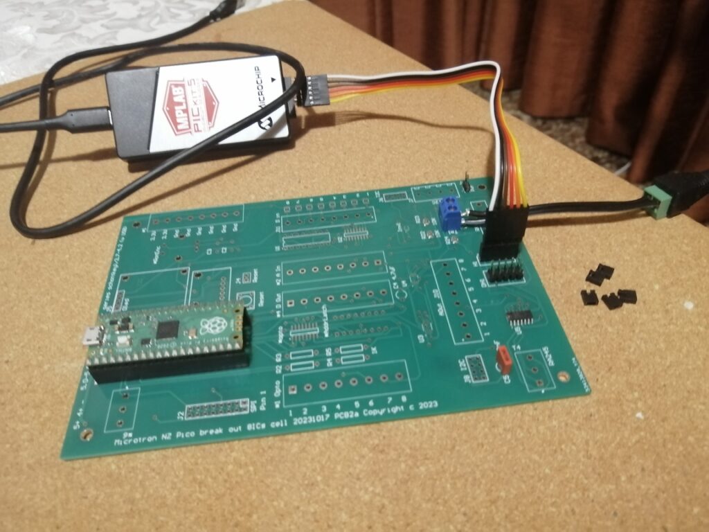
The original intention of this project was to control six PWM outputs from the PIC chip via the RPi Pico MCU. I have PWM starting, but as yet I do not have full I2C connectivity. The Internet is very sparse in examples of PIC I2C communication. Two key parts of this project will be to:
- Finish writing the partially written MPLAB program for the PIC that correctly communicates with the PIC via I2C.
- Once secure communication is established, implement the code to control the PWM outputs. They are numbered 1 to 6 in the first byte and there are two bytes for the duty cycle. It may be appropriate to have off/on commands as well.
- (Confirm the layout of the PCB. Currently this follows recommended guidelines. There are pullup resistors for SDA and SCL. Need to confirm that the programming circuitry does not interfere. However, because the PIC programs successfully and I2C data is written and read, it is unlikely that there is a problem with the PCB design. The program on the Pico gathers data to confirm that three writes and three reads occur.)
The board as it is effectively allows the upload of compiled programs from MPLAB.
Note that this approach will make possible many other programming and input/output options for use of the PIC chip. It does not need to be just PWM. There are in total 9 available connections to the PIC chip and these are programable as inputs or outputs etc.
Presently the MCU writes three bytes and reads three bytes. The data read back is contaminated by extra interrupt calls occurring on the PIC chip. One of the data values is a valid value received twice and the first value is lost. Thus, fine tuning is needed to finish correctly programming the chip.
Microtron is open to negotiation about the future of this project. It could be a small project for a student, however MPLAB offers a complex set of parameters, pin assignments and input/output modes. It is more difficult to get started on this than Arduino IDE development. There are simulation programs that can help with this e.g. Proteus, and that could be a key part of the students learning. You are likely to be able to give your students full access to such programs rather them demo versions. Proteus may be limited in terms of the number of PIC chips supported.
If a student were to complete this project to control six PWM outputs, then my only requirement would be that the program be published so that it can be used in commercial products, without the need for full disclosure of software i.e. no viral agreement/license of any kind.
This source is incomplete and it reads and writes, but extra interrupt calls cause the data to be semi-corrupted. It compiles and installs via MPLAB. The initial PWM signals initialise successfully.
- MCU units with sensors and datalogging.
- Break out boards with user interface. Suitable for datalogging and interactive function including stepper motors.
- Break out board customizations. Sensors, stepper motors, WiFi, SD cards and Fram.
- Design of circuit boards, including design of circuit boards that are a customization of a break out board pilot project.
- WiFi and server collection of data.