Pulse width modulation board with 16 channels
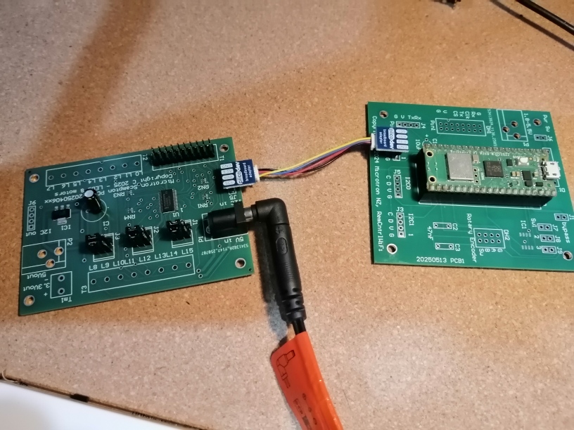
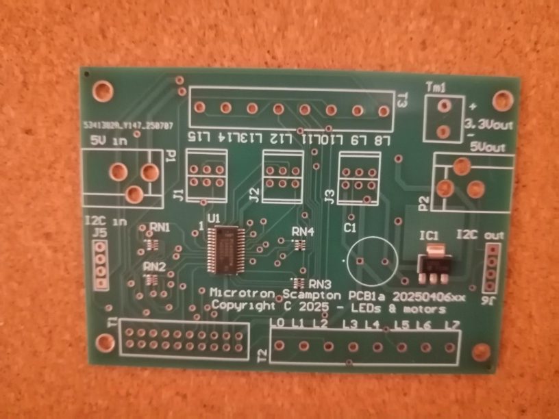
Pulse width modulation can be used to control DC (1 ch) and stepper motors (1 or 2 ch), along with servo motors and dimmable LEDs; there are 16 PWM outputs/channels per board. These boards can be daisy chained; this allows up to 62 boards per bus for one microcontroller, excluding addresses 110000 and 000011. They have there own power supply to allow loads like small LEDs to be driven directly; 5V power can be daisy chained as well as I2C. Each output has a 200 Ohm resistor in series. Below is a simple test program and a video of oscilloscope output. For secure connection a 20 pin IDC plug can be used or alternatively terminals can be used. Ribbon cable can be used to provide signal to distribution boards that provide connection to the various types of motors mentioned above. This may occur via motor drivers such as: L298N Motor Driver Module, for DC or stepper motors. Tantalum capacitors may be the best kind of capacitor to use on these boards to stabilize noisy power supply connections; some power plug socket connections can create a momentary disconnection if bumped and if there is no power smoothing capacitor the communication can crash. A past PCB 2.1mm barrel jack from Element14 was prone to causing this problem, as it had too much play and a weak spring; a Pololu version that was on hand did not cause these transitory power breaks noticeably; this problem is worth investigating if you want reliability. The following is the Scampton PWM board.
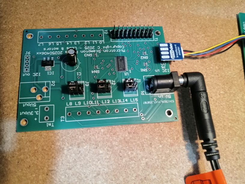
The Scampton board directly below, with 6 surface mounted chips is available for $25NZD plus postage. The board will be provided as shown. (The next version will allow the bypass of the regulator or use of I2C power; the later option requires caution as the PWM outputs will have a reduced maximum load.)
# PCA9685Test.py
# MIT License (MIT)
# Copyright (c) 2025 Microtron Ltd NZ - Stephen Eichler
# https://opensource.org/licenses/MIT

from pca9685 import PCA9685Driver
import time
p = PCA9685Driver(i2c_channel=0, scl_pin=1, sda_pin=0) # scl=Pin(1), sda=Pin(0)
print(p.i2c.scan())

while True:
    p.set_pwm_frequency(1200)
    p.set_pwm_dc_percent(0, 5)
    p.set_pwm_dc_percent(1, 10)
    p.set_pwm_dc_percent(2, 15)
    p.set_pwm_dc_percent(3, 20)
    p.set_pwm_dc_percent(4, 25)
    p.set_pwm_dc_percent(5, 30)
    p.set_pwm_dc_percent(6, 35)
    p.set_pwm_dc_percent(7, 40)
    p.set_pwm_dc_percent(8, 45)
    p.set_pwm_dc_percent(9, 50)
    p.set_pwm_dc_percent(10, 55)
    p.set_pwm_dc_percent(11, 60)
    p.set_pwm_dc_percent(12, 65)
    p.set_pwm_dc_percent(13, 70)
    p.set_pwm_dc_percent(14, 75)
    p.set_pwm_dc_percent(15, 80)
    time.sleep_ms(5000)

    p.set_pwm_frequency(50)
    p.set_pwm_dc_percent(0, 80)
    p.set_pwm_dc_percent(1, 75)
    p.set_pwm_dc_percent(2, 70)
    p.set_pwm_dc_percent(3, 65)
    p.set_pwm_dc_percent(4, 60)
    p.set_pwm_dc_percent(5, 55)
    p.set_pwm_dc_percent(6, 50)
    p.set_pwm_dc_percent(7, 45)
    p.set_pwm_dc_percent(8, 40)
    p.set_pwm_dc_percent(9, 35)
    p.set_pwm_dc_percent(10, 30)
    p.set_pwm_dc_percent(11, 25)
    p.set_pwm_dc_percent(12, 20)
    p.set_pwm_dc_percent(13, 15)
    p.set_pwm_dc_percent(14, 10)
    p.set_pwm_dc_percent(15, 5)
    time.sleep_ms(5000)
---------------------------------------------------------------------------------
# pwmpin.py
# MIT License (MIT)
# Copyright (c) 2025 Microtron Ltd NZ - Stephen Eichler
# https://opensource.org/licenses/MIT

from pca9685 import PCA9685Driver
import time

class PwmPin:

    ioaddr=None
    pinlist=None
    pinlist1=None

    @classmethod
    def updatepinlist(cls, iopin, i2c_channel, i2c_periph_addr):
        if cls.ioaddr is None or cls.pinlist is None or cls.pinlist1 is None:
            cls.ioaddr=[]
            cls.pinlist=[]
            cls.pinlist1=[]
            for i in range(0x40,0x80):
                if i != 0b11 and i != 0b110000:
                    cls.ioaddr.append(i)
                    cls.pinlist.append([])
                    cls.pinlist1.append([])
        pl=cls.pinlist if i2c_channel==0 else cls.pinlist1
        idx0 = cls.ioaddr.index(i2c_periph_addr)
        if iopin not in pl[idx0]:
            pl[idx0].append(iopin)
        else:
            raise ValueError("Duplicate pin instance " + str(iopin))


    def __init__(self, pwmpin=None, i2c_channel=0, scl_pin=1, sda_pin=0, i2c_periph_addr = 0x40, pwm_frequency=50):
        self._pcad = PCA9685Driver(i2c_channel=i2c_channel, scl_pin=scl_pin, sda_pin=sda_pin, i2c_periph_addr=i2c_periph_addr)
        self._value=0
        self._pcad.set_pwm_frequency(pwm_frequency)
        if pwmpin is None :
            raise TypeError("No index provided")
        elif pwmpin < 0 or pwmpin >= 16:
            raise ValueError("Invalid pin ID provided")
        else:
            self._pwmpin=pwmpin
        self.updatepinlist(pwmpin, i2c_channel, i2c_periph_addr)

    @property
    def value(self):
        return self._value

    @value.setter
    def value(self, value):
        if value > 100:
            self._value=100
        elif value < 0:
            self._value=0
        else:
            self._value=value
        self._pcad.set_pwm_dc_percent(self._pwmpin, self._value)

    def set_pwm_frequency(self, pwm_freq):
        self._pcad.set_pwm_frequency(self, pwm_freq)

    def servo_set_angle(self, angle):
        self._pcad.servo_set_angle(self._pwmpin, angle)

    def set_pwm_dc_ontime(self, on_time_ms):
        self._pcad.set_pwm_dc_ontime(self,self._pwmpin, on_time_ms)

    def set_pwm_dc(self, falling_edge_cnt ,rising_edge_cnt=0):
        self._pcad.set_pwm_dc(self, self._pwmpin, falling_edge_cnt ,rising_edge_cnt=0)

    def servo_set_angle(self, angle):
        self._pcad.servo_set_angle(self, self._pwmpin, angle)

    def servo_set_angle_custom(self, angle, minpulsewidth_ms, maxpulsewidth_ms):
        self._pcad.servo_set_angle_custom(self, self._pwmpin, angle, minpulsewidth_ms, maxpulsewidth_ms)

    def disable_clk(self):
        self._pcad.disable_clk(self)

    def enable_clk(self):
        self._pcad.enable_clk(self)

    def restart_clk(self):
        self._pcad.restart_clk(self)

    def sw_reset(self):
        self._pcad.sw_reset(self)
---------------------------------------------------------------------------------
# PwmPinMain.py
import pwmpin
import time

pin0 = pwmpin.PwmPin(pwmpin=0)
pin1 = pwmpin.PwmPin(pwmpin=1)
#pin2 = pwmpin.PwmPin(pwmpin=2)

#pin1a = pwmpin.PwmPin(pwmpin=1)

print(pwmpin.PwmPin.pinlist)

while True:
    pin0.value = 25
    pin1.value = 75
    print(pin0.value, pin1.value)
    time.sleep(2)
    pin0.value = 75
    pin1.value = 25
    print(pin0.value, pin1.value)
    time.sleep(2)
---------------------------------------------------------------------------------
MPY: soft reboot
[[0, 1], [], [], [], [], [], [], [], [], [], [], [], [], [], [], [], [], [], [], [], [], [], [], [], [], [], [], [], [], [], [], [], [], [], [], [], [], [], [], [], [], [], [], [], [], [], [], [], [], [], [], [], [], [], [], [], [], [], [], [], [], [], [], []]
25 75
75 25
25 75
75 25
25 75
75 25
25 75

---------------------------------------------------------------------------------
pin1a = pwmpin.PwmPin(pwmpin=1) # uncommented

MPY: soft reboot
Traceback (most recent call last):
  File "<stdin>", line 8, in <module>
  File "PwmPin.py", line 39, in __init__
  File "PwmPin.py", line 26, in updatepinlist
ValueError: Duplicate pin instance 1
>>>
---------------------------------------------------------------------------------
I2cstepper.Motor class for stepper motors
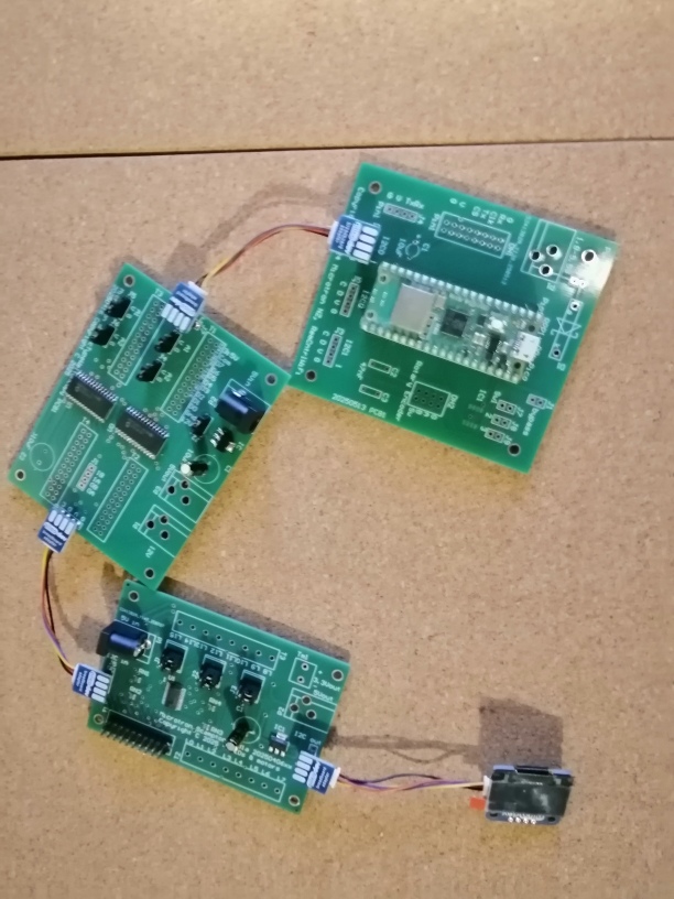
Driving stepper motors requires 4 digital IO outputs and 1 or 2 PWM outputs. The i2cstepper.Motor driver brings these together to control stepper motors. There are no pull-up resistors on the IO and PWM boards as large numbers of these can be used together, thus I have added a display containing pull-up resistors to the bus daisy chain, in this case.
# This code runs, but so far have not connected a motor
# So far this driver results in jittery stepping, however the A4988
# steppers work fine (iopinstepper1.py/iopinstepper3.py) as they did
# for the Lincoln utility board.
# i2cstepper.py
# MIT License (MIT)
# Copyright (c) 2025 Microtron Ltd NZ - Stephen Eichler
# https://opensource.org/licenses/MIT

# Forked from:
# Rui Santos & Sara Santos - Random Nerd Tutorials
# Complete project details at https://RandomNerdTutorials.com/raspberry-pi-pico-stepper-motor-micropython/
# Forked from: https://github.com/larsks/micropython-stepper-motor/blob/master/motor.py

import machine
import time
import iopin
import pwmpin

class Motor:
    stepms = 10

    # Do be defined by subclasses
    maxpos = 0
    states = []

    def __init__(self, p1, p2, p3, p4, p5, p6, bus=0, scl=1, sda=0, stepms=None,
                 ioaddr0=0x20, ioaddr1=0x21, pwmaddr=0x40, powerpercent=50):

        self._iop1=iopin.IoPin(iopin=p1, i2c_channel=bus, scl_pin=scl, sda_pin=sda,
                               i2c_periph_addr_0=ioaddr0, i2c_periph_addr_1=ioaddr1)
        self._iop2=iopin.IoPin(iopin=p2, i2c_channel=bus, scl_pin=scl, sda_pin=sda,
                               i2c_periph_addr_0=ioaddr0, i2c_periph_addr_1=ioaddr1)
        self._iop3=iopin.IoPin(iopin=p3, i2c_channel=bus, scl_pin=scl, sda_pin=sda,
                               i2c_periph_addr_0=ioaddr0, i2c_periph_addr_1=ioaddr1)
        self._iop4=iopin.IoPin(iopin=p4, i2c_channel=bus, scl_pin=scl, sda_pin=sda,
                               i2c_periph_addr_0=ioaddr0, i2c_periph_addr_1=ioaddr1)
        self._pwmp1=pwmpin.PwmPin(pwmpin=p5, i2c_channel=bus, scl_pin=scl, sda_pin=sda,
                                  i2c_periph_addr=pwmaddr)
        self._pwmp2=pwmpin.PwmPin(pwmpin=p6, i2c_channel=bus, scl_pin=scl, sda_pin=sda,
                                  i2c_periph_addr=pwmaddr)
        self.iopins = [self._iop1, self._iop2, self._iop3, self._iop4]
        self.pwmpins = [self._pwmp1, self._pwmp2]

        if stepms is not None:
            self.stepms = stepms

        self._state = 0
        self._pos = 0
        self._power = 0
        self.power(powerpercent)

    def __repr__(self):
        return '<{} @ {}>'.format(
            self.__class__.__name__,
            self.pos,
        )

    @property
    def pos(self):
        return self._pos

    def reset(self):
        self._pos = 0

    def power(self, percentval):
        if percentval < 0:
            self._power = 0
        elif percentval > 100:
            self._power = 100
        else:
            self._power = percentval

        self.pwmpins[0].value=self._power
        self.pwmpins[1].value=self._power

    def _step(self, dir):
        state = self.states[self._state]

        for i, val in enumerate(state):
            self.iopins[i].value=val

        self._state = (self._state + dir) % len(self.states)
        self._pos = (self._pos + dir) % self.maxpos

    def step(self, steps):
        dir = 1 if steps >= 0 else -1
        steps = abs(steps)

        for _ in range(steps):
            t_start = time.ticks_ms()

            self._step(dir)

            t_end = time.ticks_ms()
            t_delta = time.ticks_diff(t_end, t_start)
            time.sleep_ms(self.stepms - t_delta)

    def step_until(self, target, dir=None):
        if target < 0 or target > self.maxpos:
            raise ValueError(target)

        if dir is None:
            dir = 1 if target > self._pos else -1
            if abs(target - self._pos) > self.maxpos/2:
                dir = -dir

        while True:
            if self._pos == target:
                break
            self.step(dir)

    def step_until_angle(self, angle, dir=None):
        if angle < 0 or angle > 360:
            raise ValueError(angle)

        target = int(angle / 360 * self.maxpos)
        self.step_until(target, dir=dir)

    def step_degrees(self, degrees):
        if degrees < 0 or degrees > 360:
            raise ValueError("Degrees should be between 0 and 360")

        steps_to_take = int(degrees / 360 * self.maxpos)

        self.zero()  # Ignore the current position, start from zero
        self.step(steps_to_take)

class FullStepMotor(Motor):
    stepms = 5
    maxpos = 2048
    states = [
        [1, 1, 0, 0],
        [0, 1, 1, 0],
        [0, 0, 1, 1],
        [1, 0, 0, 1],
    ]


class HalfStepMotor(Motor):
    stepms = 3
    maxpos = 4096
    states = [
        [1, 0, 0, 0],
        [1, 1, 0, 0],
        [0, 1, 0, 0],
        [0, 1, 1, 0],
        [0, 0, 1, 0],
        [0, 0, 1, 1],
        [0, 0, 0, 1],
        [1, 0, 0, 1],
    ]
---------------------------------------------------------------------------------
# i2cstepperMain.py
import i2cstepper
import i2cdc
import pwmpin
import time
from machine import I2C, Pin
from micropython import const
import iopinstepper1
import latchiopin

# Define the IO stepper motor pins
IN0 = const(0)
IN1 = const(1)
IN2 = const(2)
IN3 = const(3)
# Define the PWM stepper motor pins
PWM0 = const(0)
PWM1 = const(1)

DCIO0 = const(4)
DCIO1 = const(5)
DCPWM0 = const(2)

SERVOPWM0 = const(4)
SERVOPWM1 = const(5)

stpdrv0=iopinstepper1.StepDrv(latchid=1)
#latch1 = latchiopin.LatchIoPin(iopinbyte=1)

i2c = I2C(id=0, scl=Pin(1), sda=Pin(0))
print(i2c.scan())

# Initialize the motors
stepper_motor = i2cstepper.FullStepMotor(IN0, IN1, IN2, IN3, PWM0, PWM1)
dc_motor = i2cdc.DcMotor(DCIO0, DCIO1, DCPWM0)
pinsv0 = pwmpin.PwmPin(pwmpin=SERVOPWM0)
pinsv1 = pwmpin.PwmPin(pwmpin=SERVOPWM1)

# Set output modes
dc_motor.reset()
# Set the current position as position 0 and set output modes
stepper_motor.reset()
stpdrv0.resetmode()
#latch1.reset()
mode = 0
min_ontime=0.6
max_ontime=2.4

direction=False
count=0
loops=0

while True:
    if mode==0:
        dc_motor.forward()
        dc_motor.power(50)
    elif mode==1:
        dc_motor.stop()
    elif mode==2:
        dc_motor.reverse()
        dc_motor.power(80)
    else:
        dc_motor.stop()

    if mode == 0:
        pinsv0.servo_set_angle_custom(90, min_ontime, max_ontime)
        pinsv1.servo_set_angle_custom(20, min_ontime, max_ontime)
    elif mode==1:
        pinsv0.servo_set_angle_custom(80, min_ontime, max_ontime)
        pinsv1.servo_set_angle_custom(40, min_ontime, max_ontime)
    elif mode==2:
        pinsv0.servo_set_angle_custom(60, min_ontime, max_ontime)
        pinsv1.servo_set_angle_custom(70, min_ontime, max_ontime)
    else:
        pinsv0.servo_set_angle_custom(40, min_ontime, max_ontime)
        pinsv1.servo_set_angle_custom(100, min_ontime, max_ontime)

    mode += 1
    if mode >= 4:
        mode = 0

    stpdrv0.DV1.direction = direction
    stpdrv0.DV1.step()

    #latch1.d0.value=1

    count += 1
    if count==16:
        count=0
        loops += 1
        direction= not direction


    #Move 50 steps in clockwise direction
    #stepper_motor.step(50)
    time.sleep(0.05) # stop for a while


---------------------------------------------------------------------------------
# This code runs, but so far have not connected a motor
# i2cdc.py
# MIT License (MIT)
# Copyright (c) 2025 Microtron Ltd NZ - Stephen Eichler
# https://opensource.org/licenses/MIT

# Forked from:
# Rui Santos & Sara Santos - Random Nerd Tutorials
# Complete project details at https://RandomNerdTutorials.com/raspberry-pi-pico-stepper-motor-micropython/
# Forked from: https://github.com/larsks/micropython-stepper-motor/blob/master/motor.py

import machine
import time
import iopin
import pwmpin

class DcMotor:
    stepms = 10

    def __init__(self, p1, p2, p3, bus=0, scl=1, sda=0, stepms=None,
                 ioaddr0=0x20, ioaddr1=0x21, pwmaddr=0x40, powerpercent=50):

        self._iop1=iopin.IoPin(iopin=p1, i2c_channel=bus, scl_pin=scl, sda_pin=sda,
                               i2c_periph_addr_0=ioaddr0, i2c_periph_addr_1=ioaddr1)
        self._iop2=iopin.IoPin(iopin=p2, i2c_channel=bus, scl_pin=scl, sda_pin=sda,
                               i2c_periph_addr_0=ioaddr0, i2c_periph_addr_1=ioaddr1)
        self._pwmp1=pwmpin.PwmPin(pwmpin=p3, i2c_channel=bus, scl_pin=scl, sda_pin=sda,
                                  i2c_periph_addr=pwmaddr)
        self.iopins = [self._iop1, self._iop2]
        self.pwmpin = self._pwmp1

        if stepms is not None:
            self.stepms = stepms

        self._state = 0
        self._pos = 0
        self._power = 0
        self.power(powerpercent)

    def __repr__(self):
        return '<{} @ {}>'.format(
            self.__class__.__name__,
            self.pos,
        )

    def reset(self):
        self.pwmpin.value=0
        self.iopins[0].value=0
        self.iopins[1].value=0

    def power(self, percentval):
        if percentval < 0:
            self._power = 0
        elif percentval > 100:
            self._power = 100
        else:
            self._power = percentval

        self.pwmpin.value=self._power

    def forward(self):
        self.iopins[0].value=1
        self.iopins[1].value=0

    def reverse(self):
        self.iopins[0].value=0
        self.iopins[1].value=1

    def stop(self):
        self.iopins[0].value=0
        self.iopins[1].value=0

    def direction(self, value, power=None):
        if value == 0:
            self.stop()
        elif value > 0:
            self.forward()
        else:
            self.reverse()

        if power is not None:
            self.power(power)
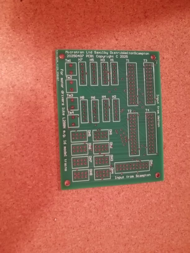
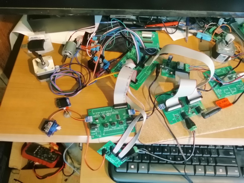
Operate several types of motors in numbers using the Saxilby Distribution Board.
Inputs Pwm from the Scampton board and IoExpansion from the Welton board (or Lincoln Utility board). See video of multiple motors. See IoExpander page. It is possible to control large numbers of stepper, DC and servo motors using these boards. Flexible design is possible and they use I2C connections to the MCU controller of your choice. A typical use might be a model train layout, where there are many sections of track under control by L298N drivers. A combination of PWM and IO outputs allow control of lights and signals where some lights may be dimmable. Various educational robotics projects are possible including a robot dog with many motors in the moving body parts; it may be possible to use AI to write some of the MicroPython code for these projects. H and DH outputs on the board have the same connections, as this layout is designed to make wiring straight forward and pluggable with secure plugs. The H connections require the separate Tm common/ground connections as the 6 pin header plugs fit the common L298N hardware drivers. Both connections supply 2 PWM and 4 digital IO outputs. The Welton connections have 8 bits/IO outputs per plug and the Scampton IDC connection has 16 PWM pins. The Scampton board currently regulates 5V power input down to 3.3V. The next versions of the Scampton board will also allow 5V operation and the bypass of the 3.3V regulator or alternatively use supply from the MCU. It does not offer to run the board from MCU I2C cable power at this time, as the intent is to supply greater load than most MCUs are rated for; if this option is added the user will receive a warning to calculate maximum current. There is huge scope for expansion of the PWM and digital IO output count, along with varied supply configurations for the various motor types; MicroPython software drivers have been provided to allow this flexibility. These options also make using power from the MCU unfeasible.