Hertfordshire Railway GUI and Interpreter – HertfordCode
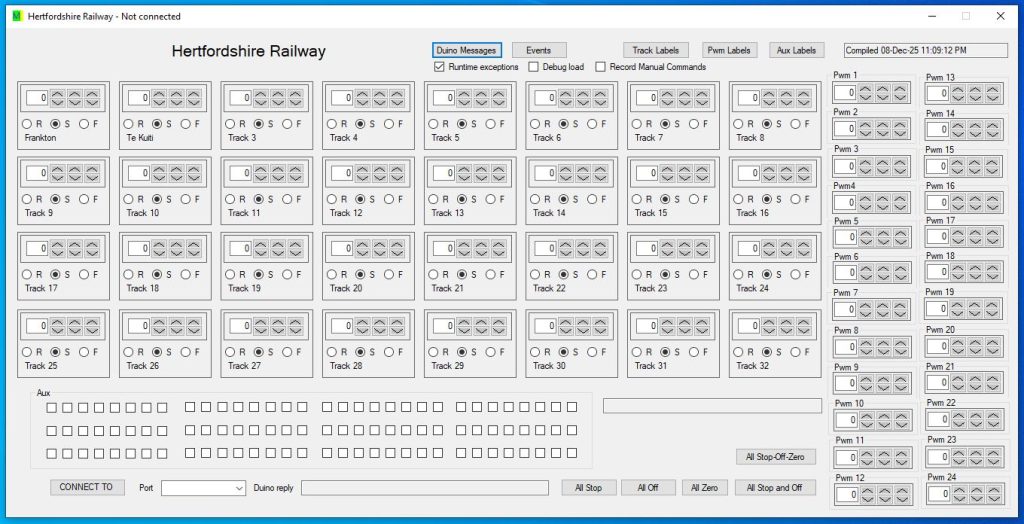
HertfordCode is based on LincolnCode and is currently under development. The GUI has been drafted as shown. The Hertfordshire Railway system is based on 32 track segments. This is a draft partially tested release and it includes running the interpreter, with tests of each hardware channel; there has been no sensor testing or testing of the ability to make decisions based on sensor readings. Download HertfordCode (2026/02/03b), the MIT license applies. You can support the development of code by Microtron NZ at this GiveSendGo website.
$ git log
commit f145dbcca795948edef07e8b088becc500a7c3dc (HEAD -> master, origin/master)
Author: stephen <stephenjeichler@gmail.com>
Date:   Tue Feb 3 19:21:59 2026 +1300

    Port read threading issue and extra calls to readline

Author: stephen <stephenjeichler@gmail.com>
Date:   Tue Feb 3 14:05:08 2026 +1300

    changed raw sense data to hex

Author: stephen <stephenjeichler@gmail.com>
Date:   Tue Feb 3 00:35:48 2026 +1300

    Adding sense data receive from MCU and debugging conditional sense

commit 284de7412ca88481b0a38bf19235f70e73311a3e
Author: stephen <stephenjeichler@gmail.com>
Date:   Sun Feb 1 17:45:41 2026 +1300

    Changed to UTC in order to prevent daylight saving issues

commit 776c2542677b5053e9572a4bcf2a375282515fab
Author: stephen <stephenjeichler@gmail.com>
Date:   Thu Jan 29 23:21:21 2026 +1300

    added extra dumps of speed, dir, aux and pwm, for each command

commit a2cd49f8eb101bca72402734342b83e17f77942d
Author: stephen <stephenjeichler@gmail.com>
Date:   Thu Jan 29 01:04:50 2026 +1300

    updated time base, included days and centiseconds

commit cc25ceeddc6bcf2d19334ec480c80ab9809ce1c7
Author: stephen <stephenjeichler@gmail.com>
Date:   Tue Jan 27 19:44:43 2026 +1300

    shrink form and debugged timer run

commit f1e55ee92f13808ef99e8af1445c214252bfcaae
Author: stephen <stephenjeichler@gmail.com>
Date:   Tue Dec 9 15:17:55 2025 +1300

    test commit

commit 3aa9b7154df56deefdab99633ed46b26130d21b0
Author: stephen <stephenjeichler@gmail.com>
Date:   Tue Dec 9 13:52:49 2025 +1300

    show any reply

commit 21d234d488a22a437abd3120c3a83689e6a8839e
Author: stephen <stephenjeichler@gmail.com>
Date:   Mon Dec 8 23:04:25 2025 +1300

    Updated key commands

commit 32c8b84ece394fe619ce5d77ece46f3d8bd43380
Author: stephen <stephenjeichler@gmail.com>
Date:   Mon Dec 8 18:25:43 2025 +1300

    Expanded pwm and aux control count

commit 73b60009f66859a4d118e64777a8828eaba80569
Author: stephen <stephenjeichler@gmail.com>
Date:   Sun Dec 7 16:25:02 2025 +1300

    Debug load behaviour

commit c206bf4998db64f99a7b601c0488a19ee936cd24
Author: stephen <stephenjeichler@gmail.com>
Date:   Sun Dec 7 14:15:08 2025 +1300

    Add project files.

commit 70bb77b7f5234c21e187d029235ac7c60f775cd0
Author: stephen <stephenjeichler@gmail.com>
Date:   Sun Dec 7 14:15:05 2025 +1300

commit 70bb77b7f5234c21e187d029235ac7c60f775cd0
Author: stephen <stephenjeichler@gmail.com>
Date:   Sun Dec 7 14:15:05 2025 +1300

    Add .gitattributes and .gitignore.
:
Hertford code includes attempts to handle exceptions in a variety of ways, that are controlled by the user. The idea is that new Hertford interpreter code will be tested and debugged with exceptions on and then when a live run is carried out program halting exceptions can be disabled, but they will still be immediately displayed and recorded, without halting the program automatically. This software seems to run satisfactorily with Wine on Ubuntu, though many options for the com port may occur; I need to find a work around for populating the Combobox more sensibly. Initial syntax testing exceptions as the interpreter code loads are treated differently to interpreter runtime exceptions. “Debug Load” allows program halting exceptions to occur during Hertford code loading; this allows fully featured debugging to occur. If “Debug Load” is unchecked, then the error message will be displayed, but the program may continue, allowing in particular manual control to still occur. It is possible to observe JSF (Joint Strike Fighter) requirements for no exceptions and no recursion; exceptions are switched off when “runtime exceptions” and debugging are switched off, but the loading process still can show a warning MessageBox and then continue when that box is closed; note that no further interpreter code is loaded after the syntax error; also note, that these messages result from load exceptions that are handled and error testing occurs to the maximum extent that is considered safe. There may still be exceptions lurking in the standard command methods used; this is due to the design of the C# language and .NET; it is conceivable to put a try loop around every single command that could contain a possible exception. It is also considered that using return codes to fully replace exceptions, creates greater complexity and unreadability of code. I note that, the SerialPort.ReadLine-TimeOut exception is unavoidable; a return code would be better. I also think that an exception true/false syntax that can deactivate the try clause would be very useful, for switching between interpreter debugging mode and critical run mode, as hardly any change to the code would be needed to be able to run without exceptions; clearly some return diagnostics could still be used where needed. This is not C++ and so memory allocation is different, but most memory hungry code occurs during loading of the interpreter code; objects like forms that can require manual disposal, remain to be fully checked. The methods “readTimeSequenceHelper” and “buttonRun_Click” have long sequences of conditional statements, depending on how long the HertfordCode interpreter program is; the limit of 20 is likely to be broken, however the level of complexity is not expected to be excessive, as the pattern is highly repetitive. C# and .NET may have other weaknesses not addressed or known here.
My view is that C# could take a step closer to JSF compatibility, by offering method variants that do not trigger traditional potentially program halting exceptions, but rather have an extra first parameter inserted that is returned by reference and is a “ReferenceException” object. The object would be interrogated after command execution, the first object parameter to test would be “ExceptionOccurred”. Every attempt would be made to limit the circumstances where a ReferenceException occurs. For example str.SubString produces a sensible/logical result, even when the maxlength parameter exceeds the length of the string. Ideally there would be a way (a compiler switch) to globally disable all methods that contain a traditional high risk exception. It would also be necessary to turn off the garbage collector and fulfil other requirements for real time operating system use, including an improved time base e.g. delay(1), delay for 1 millisecond; microsecond delays would also be useful. C# use is attractive over C/C++ in terms of being less error prone and more convenient in terms of GUI design. It may be that the best performance occurs running VS .NET programs on Linux using Wine, as Wine stability matures. Linux is more attractive than Windows for execution over long periods of time, as Linux is usually more stable, in this regard.
ReferenceException re = new ReferenceException;
string str = serialPort.ReadLine(out re);
if (re.ExceptionOccurred)
{
    if(re.ExceptionType == ReferenceException.TimeOutException)
        return;
    ostream?.Write("Ex: " + re.ExceptionType + " - " + re.message);
    return;
}
// This is a sample of Hertford code, used for syntax testing
00:00:00 callbackif 4 once-3   // check sensor 4, trigger once
//00:00:00 callbackifgap 4 3
00:00:00 track 0 stop
00:00:00 aux 0 off
00:00:00 program 0 stop
00:00:00 callbackif 4 end

00:00:00 callbackifnot 3 once-3  // check sensor 3 off, trigger once
//00:00:00 callbackifnotgap 3 2
//00:00:00 track 2 forward
00:00:00 sense 2 if
00:00:00 track 1 forward-100
00:00:00 sense 2 else
00:00:00 track 32 reverse-50
00:00:00 sense 2 end
00:00:00 callbackifnot 3 end

00:00:00 callbackif 9 repeat  // check sensor 9, trigger continuously
00:00:00 callbackif 9 ignore
00:00:00 track 1 stop
00:00:00 callbackif 9 end

00:00:00 callback 20 repeat  // trigger continuously
00:00:00 callback 20 ignore
00:00:00 track 1 stop
00:00:00 callback 20 end


00:00:05 track 3 forward-100
00:00:05 track 5 reverse-50
00:00:05 callbackifnotgap 3 1
00:00:08 track 5 5-inc
00:00:15 track 7 stop
00:00:15 callbackifnotcount 3 repeat // reset counter
00:00:15 callbackgap 20 3
00:00:17 track 0 stop    //stop all tracks
00:00:18 aux 0 on       //turn all auxiliaries on
00:00:18 callback 20 ignore

00:00:19 pwm 0 0
00:00:19 pwm 8 125
00:00:19 callback 0 ignore   // disable only non conditional callbacks
00:00:19 sense 3 if
00:00:19 track 2 forward
//00:00:19 callbackifnotgap 3 1
00:00:19 sense 3 ignore
00:00:19 trackstaterev 6 if
00:00:19 track 2 stop
00:00:19 trackstaterev 6 end
00:00:19 sense 3 else
00:00:19 track 2 reverse
00:00:19 aux 2 off
00:00:19 sense 3 end
00:00:19 callbackcount 20 once-2
//00:00:21 callbackcount 21 once-2

00:00:20 analogread 15 if-200-300
00:00:20 track 2 stop
00:00:20 analogread 15 end
00:00:20 analogread 14 if->-300
00:00:20 track 2 stop
00:00:20 analogread 14 end

00:00:21 sense 4 ifnot
00:00:21 track 2 stop
00:00:21 callbackifnotexp 3 if
00:00:21 track 5 reverse
00:00:21 callbackifnotexp 3 else
00:00:21 track 5 forward
00:00:21 callbackifnotexp 3 end
00:00:21 sense 4 end
00:00:21 callbackif 3 restore
00:00:21 callback 20 restore
00:00:21 callbackexp 20 ifnot
//00:00:21 callbackexp 20 ifnot
00:00:21 track 2 forward
00:00:21 callbackexp 20 end

00:00:22 callbackifnot 0 restore
00:00:22 sense 4 ignore
00:00:22 callback 20 execute-force

00:00:23 sense 4 if
00:00:23 track 2 stop
00:00:23 sense 4 end
00:00:23 callback 20 execute

00:00:23 trackstate 6 if
00:00:23 track 2 stop
00:00:23 trackstate 6 end

00:00:23 auxstate 5 if
00:00:23 track 3 stop
00:00:23 auxstate 5 end

00:00:24 sense 4 restore

===========================================================================
// This is a sample of Hertford code that is being tested with the hardware
00:00:01 track 1 forward-50
00:00:02 track 1 stop
00:00:02 track 2 forward-40
00:00:03 track 1 reverse-10
00:00:03 track 2 stop
00:00:03 track 3 forward-10
00:00:04 track 1 stop
00:00:04 track 2 reverse-50
00:00:04 track 3 stop
00:00:04.5 track 4 forward-50
00:00:05 track 2 stop
00:00:05 track 3 reverse-30
00:00:05 track 4 stop
00:00:05.5 track 5 forward-30
00:00:06 track 3 stop
00:00:06 track 4 reverse-30
00:00:06 track 5 stop
00:00:06.5 track 6 forward-30
00:00:07 track 4 stop
00:00:07 track 5 reverse-40
00:00:07 track 6 stop
00:00:07.5 track 7 forward-40
00:00:08 track 5 stop
00:00:08 track 6 reverse-20
00:00:08 track 7 stop
00:00:08.5 track 8 forward-20
00:00:09 track 6 stop
00:00:09 track 7 reverse-100
00:00:09 track 8 stop
00:00:09.5 track 9 forward-100
00:00:10 track 7 stop
00:00:10 track 8 reverse-50
00:00:10 track 9 stop
00:00:10.5 track 10 forward-50
00:00:11 track 8 stop
00:00:11 track 9 reverse-70
00:00:11 track 10 stop
00:00:11.5 track 11 forward-70
00:00:12 track 9 stop
00:00:12 track 10 reverse-10
00:00:12 track 11 stop
00:00:12 track 12 forward-10
00:00:13 track 10 stop
00:00:13 track 11 reverse-80
00:00:13 track 12 stop
00:00:13 track 13 forward-80
00:00:14 track 11 stop
00:00:14 track 12 reverse-40
00:00:14 track 13 stop
00:00:14 track 14 forward-40
00:00:15 track 12 stop
00:00:15 track 13 reverse-20
00:00:15 track 14 stop
00:00:15 track 15 forward-20
00:00:16 track 13 stop
00:00:16 track 14 reverse-60
00:00:16 track 15 stop
00:00:16 track 16 forward-60
00:00:17 track 14 stop
00:00:17 track 15 reverse-40
00:00:17 track 16 stop
00:00:17 track 17 forward-40
00:00:18 track 15 stop
00:00:18 track 16 reverse-20
00:00:18 track 17 stop
00:00:18 track 18 forward-20
00:00:19 track 16 stop
00:00:19 track 17 reverse-10
00:00:19 track 18 stop
00:00:19 track 19 forward-10
00:00:20 track 17 stop
00:00:20 track 18 reverse-100
00:00:20 track 19 stop
00:00:20 track 20 forward-100
00:00:21 track 18 stop
00:00:21 track 19 reverse-20
00:00:21 track 20 stop
00:00:21 track 21 forward-20
00:00:22 track 19 stop
00:00:22 track 20 reverse-10
00:00:22 track 21 stop
00:00:22 track 22 forward-10
00:00:23 track 20 stop
00:00:23 track 21 reverse-30
00:00:23 track 22 stop
00:00:23 track 23 forward-30
00:00:24 track 21 stop
00:00:24 track 22 reverse-60
00:00:24 track 23 stop
00:00:24 track 24 forward-60
00:00:25 track 22 stop
00:00:25 track 23 reverse-30
00:00:25 track 24 stop
00:00:25 track 25 forward-30
00:00:26 track 23 stop
00:00:26 track 24 reverse-20
00:00:26 track 25 stop
00:00:26 track 26 forward-20
00:00:27 track 24 stop
00:00:27 track 25 reverse-30
00:00:27 track 26 stop
00:00:27 track 27 forward-30
00:00:28 track 25 stop
00:00:28 track 26 reverse-20
00:00:28 track 27 stop
00:00:28 track 28 forward-20
00:00:29 track 26 stop
00:00:29 track 27 reverse-90
00:00:29 track 28 stop
00:00:29 track 29 forward-90
00:00:30 track 27 stop
00:00:30 track 28 reverse-90
00:00:30 track 29 stop
00:00:30 track 30 forward-90
00:00:31 track 28 stop
00:00:31 track 29 reverse-80
00:00:31 track 30 stop
00:00:31 track 31 forward-80
00:00:32 track 29 stop
00:00:32 track 30 reverse-10
00:00:32 track 31 stop
00:00:32 track 32 forward-10
00:00:33 track 30 stop
00:00:33 track 31 reverse-40
00:00:33 track 32 stop
00:00:34 track 31 stop
00:00:34 track 32 reverse-50
00:00:35 track 32 stop

00:00:35.5 sense 1 ifnot         // Conditional test
00:00:35.5 track 1 forward       // sense 0, ignore 0 = 1
00:00:35.5 sense 1 ignore
00:00:35.5 sense 1 else          // sense 1, ignore 0 = 0
00:00:35.5 track 1 reverse
//00:00:35.5 sense 1 ignore
00:00:35.5 sense 1 end

00:00:36 aux 1 on   // relay on

00:00:36.5 sense 1 if         // Conditional test
00:00:36.5 track 2 forward    //
00:00:36.5 sense 1 else
00:00:36.5 track 2 reverse
00:00:36.5 sense 1 end

00:00:37 aux 2 on

00:00:37.5 sense 1 ifnot         // Conditional test sense 0, ignore 1 = 1
00:00:37.5 track 3 forward       //                  sense 1, ignore 1 = 1
00:00:37.5 sense 1 restore
00:00:37.5 sense 1 else
00:00:37.5 track 3 reverse
00:00:37.5 sense 1 end

00:00:37 aux 1 off
00:00:38 aux 3 on
00:00:38 aux 2 off
00:00:39 aux 4 on
00:00:39 aux 3 off
00:00:40 aux 5 on
00:00:40 aux 4 off
00:00:41 aux 6 on
00:00:41 aux 5 off
00:00:42 aux 7 on
00:00:42 aux 6 off
00:00:43 aux 8 on
00:00:43 aux 7 off
00:00:44 aux 8 off
00:00:46 pwm 1 10   // servo angle
00:00:47 pwm 1 20
00:00:48 pwm 1 30
00:00:49 pwm 1 40
00:00:50 pwm 1 50
00:00:51 pwm 1 60
00:00:52 pwm 1 70
00:00:53 pwm 1 80
00:00:54 pwm 1 90
00:00:55 pwm 1 100
00:00:56 pwm 1 110
00:00:57 pwm 1 120
00:00:58 pwm 1 130
00:00:59 pwm 1 140
00:01:00 pwm 1 150
00:01:01 pwm 1 160
00:01:02 pwm 1 170
00:01:02 pwm 1 30
00:01:03 pwm 1 90
00:01:04 pwm 1 120
00:01:05 pwm 1 60
00:01:06 pwm 1 120
00:01:07 pwm 1 90
00:01:08 pwm 1 60
00:01:09 pwm 1 170
00:01:10 pwm 1 150
00:01:11 pwm 1 140
00:01:12 pwm 1 130
00:01:13 pwm 1 80
00:01:14 pwm 1 130
00:01:15 pwm 1 20
00:01:16 pwm 1 40
00:01:17 pwm 1 60
00:01:18 pwm 1 140
00:01:19 pwm 1 160
00:01:20 pwm 1 110
00:01:21 pwm 1 170
00:01:22 pwm 1 80
00:01:23 pwm 1 30
00:01:24 pwm 1 100
00:01:25 pwm 1 50
00:01:26 pwm 1 20
Hertford model railway function test
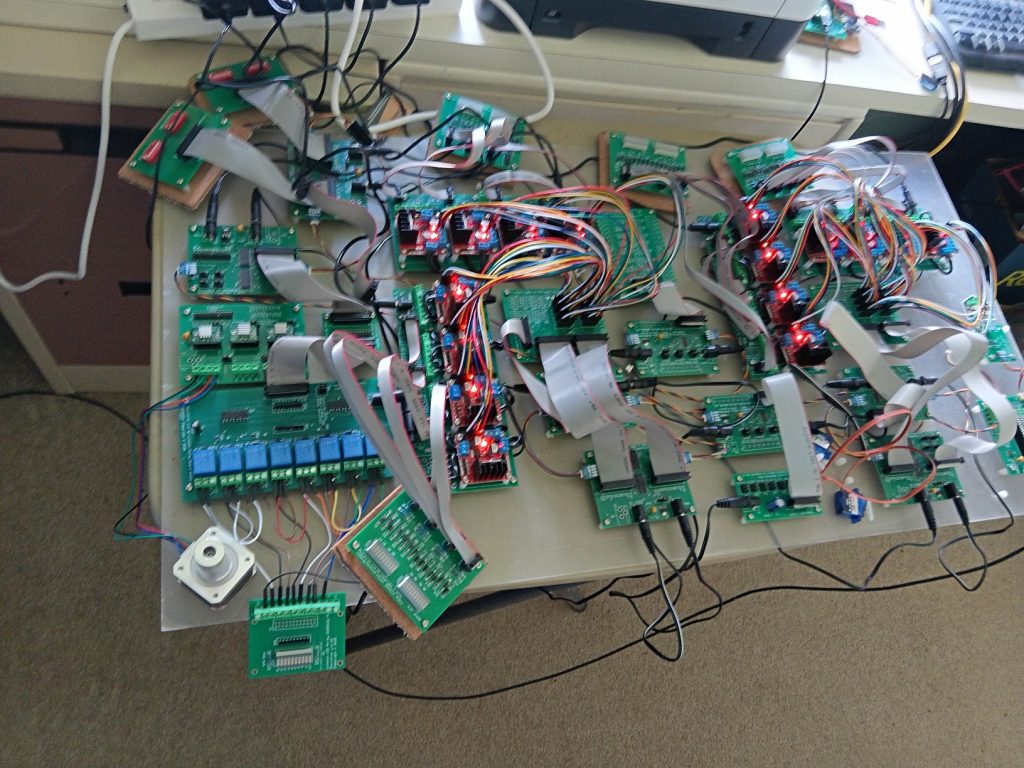
A preliminary function test of the HertfordCode program in conjunction with the hardware shown has been carried out. Included is the video of a manual test, along with video of a Hertfordcode automated test and below is the python code that receives the text string signals from HertfordshireRailway.exe. Of more relevance to non-programmers is the code above, that can be used to control your model railway like clockwork; this has commands to start and stop individual trains, along with commands to control signals and even to read train detection sensors (I have not designed these yet, but they may already be on the market) and make a decision based on the result. Note that the circuit boards that are not attached to the acrylic sheet are diagnostic and are temporary.
A successful test using the GUI program to control the hardware has occurred. The two controls tested were train forward/reverse along with speed and the second was controlling a relay, that could be used for many different purposes in a model railway. The hardware is setup to power model trains, as it is. It is modular so that if any problems occur, one small unit causing the problem can be replaced.
# main.py - i2cdcMain4.py
# MIT License (MIT)
# Copyright (c) 2024 Microtron Ltd NZ - Stephen Eichler
# https://opensource.org/licenses/MIT
# Written 23/1/2026
from machine import Pin, I2C
import i2cdc
import time
from micropython import const
import sys, select
import iopin
import pwmpin
import ioinput
import iopinstep3sw
import latchiopin

spoll = select.poll()
spoll.register(sys.stdin, select.POLLIN)

SCL = const(1)
SDA = const(0)

i2c = I2C(id=0, scl=Pin(SCL), sda=Pin(SDA))
#i2c = I2C(id=0, scl=Pin(21), sda=Pin(20))
#i2c = I2C(id=0, scl=Pin(1), sda=Pin(0))

#pwm01val010-
#aux01valOnn-
#aux01valOff-
#track01F100-

DC0IO0 = const(0)
DC0IO1 = const(1)
DC0PWM0 = const(0)
DC1IO0 = const(2)
DC1IO1 = const(3)
DC1PWM0 = const(1)
DC2IO0 = const(4)
DC2IO1 = const(5)
DC2PWM0 = const(2)
DC3IO0 = const(6)
DC3IO1 = const(7)
DC3PWM0 = const(3)
DC4IO0 = const(8)
DC4IO1 = const(9)
DC4PWM0 = const(4)
DC5IO0 = const(10)
DC5IO1 = const(11)
DC5PWM0 = const(5)
DC6IO0 = const(12)
DC6IO1 = const(13)
DC6PWM0 = const(6)
DC7IO0 = const(14)
DC7IO1 = const(15)
DC7PWM0 = const(7)

DC8IO0 = const(16)
DC8IO1 = const(17)
DC8PWM0 = const(8)
DC9IO0 = const(18)
DC9IO1 = const(19)
DC9PWM0 = const(9)
DC10IO0 = const(20)
DC10IO1 = const(21)
DC10PWM0 = const(10)
DC11IO0 = const(22)
DC11IO1 = const(23)
DC11PWM0 = const(11)
DC12IO0 = const(24)
DC12IO1 = const(25)
DC12PWM0 = const(12)
DC13IO0 = const(26)
DC13IO1 = const(27)
DC13PWM0 = const(13)
DC14IO0 = const(28)
DC14IO1 = const(29)
DC14PWM0 = const(14)
DC15IO0 = const(30)
DC15IO1 = const(31)
DC15PWM0 = const(15)

mode = 0

def i2c_scan(i2c):
    try:
        devices = i2c.scan()
        if len(devices) == 0:
            print("No I2C devices found.")
        else:
            print("Found the following I2C devices:")
            for device in devices:
                print(f"Device address: 0x{device:02X}")
    except OSError as e:
        print(f"An error occurred during the I2C scan: {e}")

#i2c_scan(i2c)

# i2c = I2C(scl=Pin(21), sda=Pin(20))

dc_motor0 = i2cdc.DcMotor(DC0IO0, DC0IO1, DC0PWM0, bus=0, scl=SCL, sda=SDA, powerpercent=0)
dc_motor1 = i2cdc.DcMotor(DC1IO0, DC1IO1, DC1PWM0, bus=0, scl=SCL, sda=SDA, powerpercent=0)
dc_motor2 = i2cdc.DcMotor(DC2IO0, DC2IO1, DC2PWM0, bus=0, scl=SCL, sda=SDA, powerpercent=0)
dc_motor3 = i2cdc.DcMotor(DC3IO0, DC3IO1, DC3PWM0, bus=0, scl=SCL, sda=SDA, powerpercent=0)
dc_motor4 = i2cdc.DcMotor(DC4IO0, DC4IO1, DC4PWM0, bus=0, scl=SCL, sda=SDA, powerpercent=0)
dc_motor5 = i2cdc.DcMotor(DC5IO0, DC5IO1, DC5PWM0, bus=0, scl=SCL, sda=SDA, powerpercent=0)
dc_motor6 = i2cdc.DcMotor(DC6IO0, DC6IO1, DC6PWM0, bus=0, scl=SCL, sda=SDA, powerpercent=0)
dc_motor7 = i2cdc.DcMotor(DC7IO0, DC7IO1, DC7PWM0, bus=0, scl=SCL, sda=SDA, powerpercent=0)

dc_motor8 = i2cdc.DcMotor(DC8IO0, DC8IO1, DC8PWM0, bus=0, scl=SCL, sda=SDA, powerpercent=0)
dc_motor9 = i2cdc.DcMotor(DC9IO0, DC9IO1, DC9PWM0, bus=0, scl=SCL, sda=SDA, powerpercent=0)
dc_motor10 = i2cdc.DcMotor(DC10IO0, DC10IO1, DC10PWM0, bus=0, scl=SCL, sda=SDA, powerpercent=0)
dc_motor11 = i2cdc.DcMotor(DC11IO0, DC11IO1, DC11PWM0, bus=0, scl=SCL, sda=SDA, powerpercent=0)
dc_motor12 = i2cdc.DcMotor(DC12IO0, DC12IO1, DC12PWM0, bus=0, scl=SCL, sda=SDA, powerpercent=0)
dc_motor13 = i2cdc.DcMotor(DC13IO0, DC13IO1, DC13PWM0, bus=0, scl=SCL, sda=SDA, powerpercent=0)
dc_motor14 = i2cdc.DcMotor(DC14IO0, DC14IO1, DC14PWM0, bus=0, scl=SCL, sda=SDA, powerpercent=0)
dc_motor15 = i2cdc.DcMotor(DC15IO0, DC15IO1, DC15PWM0, bus=0, scl=SCL, sda=SDA, powerpercent=0)

dc_motor16 = i2cdc.DcMotor(DC0IO0, DC0IO1, DC0PWM0, bus=0, scl=SCL, sda=SDA, powerpercent=0, ioaddr0=0x22, ioaddr1=0x23, pwmaddr=0x44)
dc_motor17 = i2cdc.DcMotor(DC1IO0, DC1IO1, DC1PWM0, bus=0, scl=SCL, sda=SDA, powerpercent=0, ioaddr0=0x22, ioaddr1=0x23, pwmaddr=0x44)
dc_motor18 = i2cdc.DcMotor(DC2IO0, DC2IO1, DC2PWM0, bus=0, scl=SCL, sda=SDA, powerpercent=0, ioaddr0=0x22, ioaddr1=0x23, pwmaddr=0x44)
dc_motor19 = i2cdc.DcMotor(DC3IO0, DC3IO1, DC3PWM0, bus=0, scl=SCL, sda=SDA, powerpercent=0, ioaddr0=0x22, ioaddr1=0x23, pwmaddr=0x44)
dc_motor20 = i2cdc.DcMotor(DC4IO0, DC4IO1, DC4PWM0, bus=0, scl=SCL, sda=SDA, powerpercent=0, ioaddr0=0x22, ioaddr1=0x23, pwmaddr=0x44)
dc_motor21 = i2cdc.DcMotor(DC5IO0, DC5IO1, DC5PWM0, bus=0, scl=SCL, sda=SDA, powerpercent=0, ioaddr0=0x22, ioaddr1=0x23, pwmaddr=0x44)
dc_motor22 = i2cdc.DcMotor(DC6IO0, DC6IO1, DC6PWM0, bus=0, scl=SCL, sda=SDA, powerpercent=0, ioaddr0=0x22, ioaddr1=0x23, pwmaddr=0x44)
dc_motor23 = i2cdc.DcMotor(DC7IO0, DC7IO1, DC7PWM0, bus=0, scl=SCL, sda=SDA, powerpercent=0, ioaddr0=0x22, ioaddr1=0x23, pwmaddr=0x44)

dc_motor24 = i2cdc.DcMotor(DC8IO0, DC8IO1, DC8PWM0, bus=0, scl=SCL, sda=SDA, powerpercent=0, ioaddr0=0x22, ioaddr1=0x23, pwmaddr=0x44)
dc_motor25 = i2cdc.DcMotor(DC9IO0, DC9IO1, DC9PWM0, bus=0, scl=SCL, sda=SDA, powerpercent=0, ioaddr0=0x22, ioaddr1=0x23, pwmaddr=0x44)
dc_motor26 = i2cdc.DcMotor(DC10IO0, DC10IO1, DC10PWM0, bus=0, scl=SCL, sda=SDA, powerpercent=0, ioaddr0=0x22, ioaddr1=0x23, pwmaddr=0x44)
dc_motor27 = i2cdc.DcMotor(DC11IO0, DC11IO1, DC11PWM0, bus=0, scl=SCL, sda=SDA, powerpercent=0, ioaddr0=0x22, ioaddr1=0x23, pwmaddr=0x44)
dc_motor28 = i2cdc.DcMotor(DC12IO0, DC12IO1, DC12PWM0, bus=0, scl=SCL, sda=SDA, powerpercent=0, ioaddr0=0x22, ioaddr1=0x23, pwmaddr=0x44)
dc_motor29 = i2cdc.DcMotor(DC13IO0, DC13IO1, DC13PWM0, bus=0, scl=SCL, sda=SDA, powerpercent=0, ioaddr0=0x22, ioaddr1=0x23, pwmaddr=0x44)
dc_motor30 = i2cdc.DcMotor(DC14IO0, DC14IO1, DC14PWM0, bus=0, scl=SCL, sda=SDA, powerpercent=0, ioaddr0=0x22, ioaddr1=0x23, pwmaddr=0x44)
dc_motor31 = i2cdc.DcMotor(DC15IO0, DC15IO1, DC15PWM0, bus=0, scl=SCL, sda=SDA, powerpercent=0, ioaddr0=0x22, ioaddr1=0x23, pwmaddr=0x44)

dc_motor = [dc_motor0,dc_motor1,dc_motor2,dc_motor3,dc_motor4,dc_motor5,dc_motor6,dc_motor7,
            dc_motor8,dc_motor9,dc_motor10,dc_motor11,dc_motor12,dc_motor13,dc_motor14,dc_motor15,
            dc_motor16,dc_motor17,dc_motor18,dc_motor19,dc_motor20,dc_motor21,dc_motor22,dc_motor23,
            dc_motor24,dc_motor25,dc_motor26,dc_motor27,dc_motor28,dc_motor29,dc_motor30,dc_motor31]

ioinput1 = ioinput.IOINPUT(i2c, 0x24)
ioinput2 = ioinput.IOINPUT(i2c, 0x25)

'''
iopin0 = iopin.IoPin(iopin=0, i2c_channel=0, scl_pin=SCL, sda_pin=SDA,
                               i2c_periph_addr_0=0x26, i2c_periph_addr_1=0x27)
iopin1 = iopin.IoPin(iopin=1, i2c_channel=0, scl_pin=SCL, sda_pin=SDA,
                               i2c_periph_addr_0=0x26, i2c_periph_addr_1=0x27)
iopin2 = iopin.IoPin(iopin=2, i2c_channel=0, scl_pin=SCL, sda_pin=SDA,
                               i2c_periph_addr_0=0x26, i2c_periph_addr_1=0x27)
iopin3 = iopin.IoPin(iopin=3, i2c_channel=0, scl_pin=SCL, sda_pin=SDA,
                               i2c_periph_addr_0=0x26, i2c_periph_addr_1=0x27)
iopin4 = iopin.IoPin(iopin=4, i2c_channel=0, scl_pin=SCL, sda_pin=SDA,
                               i2c_periph_addr_0=0x26, i2c_periph_addr_1=0x27)
iopin5 = iopin.IoPin(iopin=5, i2c_channel=0, scl_pin=SCL, sda_pin=SDA,
                               i2c_periph_addr_0=0x26, i2c_periph_addr_1=0x27)
iopin6 = iopin.IoPin(iopin=6, i2c_channel=0, scl_pin=SCL, sda_pin=SDA,
                               i2c_periph_addr_0=0x26, i2c_periph_addr_1=0x27)
iopin7 = iopin.IoPin(iopin=7, i2c_channel=0, scl_pin=SCL, sda_pin=SDA,
                               i2c_periph_addr_0=0x26, i2c_periph_addr_1=0x27)
iopin8 = iopin.IoPin(iopin=8, i2c_channel=0, scl_pin=SCL, sda_pin=SDA,
                               i2c_periph_addr_0=0x26, i2c_periph_addr_1=0x27)
iopin9 = iopin.IoPin(iopin=9, i2c_channel=0, scl_pin=SCL, sda_pin=SDA,
                               i2c_periph_addr_0=0x26, i2c_periph_addr_1=0x27)
iopin10 = iopin.IoPin(iopin=10, i2c_channel=0, scl_pin=SCL, sda_pin=SDA,
                               i2c_periph_addr_0=0x26, i2c_periph_addr_1=0x27)
iopin11 = iopin.IoPin(iopin=11, i2c_channel=0, scl_pin=SCL, sda_pin=SDA,
                               i2c_periph_addr_0=0x26, i2c_periph_addr_1=0x27)
iopin12 = iopin.IoPin(iopin=12, i2c_channel=0, scl_pin=SCL, sda_pin=SDA,
                               i2c_periph_addr_0=0x26, i2c_periph_addr_1=0x27)
iopin13 = iopin.IoPin(iopin=13, i2c_channel=0, scl_pin=SCL, sda_pin=SDA,
                               i2c_periph_addr_0=0x26, i2c_periph_addr_1=0x27)
iopin14 = iopin.IoPin(iopin=14, i2c_channel=0, scl_pin=SCL, sda_pin=SDA,
                               i2c_periph_addr_0=0x26, i2c_periph_addr_1=0x27)
iopin15 = iopin.IoPin(iopin=15, i2c_channel=0, scl_pin=SCL, sda_pin=SDA,
                               i2c_periph_addr_0=0x26, i2c_periph_addr_1=0x27)
iopin16 = iopin.IoPin(iopin=16, i2c_channel=0, scl_pin=SCL, sda_pin=SDA,
                               i2c_periph_addr_0=0x26, i2c_periph_addr_1=0x27)
iopin17 = iopin.IoPin(iopin=17, i2c_channel=0, scl_pin=SCL, sda_pin=SDA,
                               i2c_periph_addr_0=0x26, i2c_periph_addr_1=0x27)
iopin18 = iopin.IoPin(iopin=18, i2c_channel=0, scl_pin=SCL, sda_pin=SDA,
                               i2c_periph_addr_0=0x26, i2c_periph_addr_1=0x27)
iopin19 = iopin.IoPin(iopin=19, i2c_channel=0, scl_pin=SCL, sda_pin=SDA,
                               i2c_periph_addr_0=0x26, i2c_periph_addr_1=0x27)
iopin20 = iopin.IoPin(iopin=20, i2c_channel=0, scl_pin=SCL, sda_pin=SDA,
                               i2c_periph_addr_0=0x26, i2c_periph_addr_1=0x27)
iopin21 = iopin.IoPin(iopin=21, i2c_channel=0, scl_pin=SCL, sda_pin=SDA,
                               i2c_periph_addr_0=0x26, i2c_periph_addr_1=0x27)
iopin22 = iopin.IoPin(iopin=22, i2c_channel=0, scl_pin=SCL, sda_pin=SDA,
                               i2c_periph_addr_0=0x26, i2c_periph_addr_1=0x27)
iopin23 = iopin.IoPin(iopin=23, i2c_channel=0, scl_pin=SCL, sda_pin=SDA,
                               i2c_periph_addr_0=0x26, i2c_periph_addr_1=0x27)
iopin24 = iopin.IoPin(iopin=24, i2c_channel=0, scl_pin=SCL, sda_pin=SDA,
                               i2c_periph_addr_0=0x26, i2c_periph_addr_1=0x27)
iopin25 = iopin.IoPin(iopin=25, i2c_channel=0, scl_pin=SCL, sda_pin=SDA,
                               i2c_periph_addr_0=0x26, i2c_periph_addr_1=0x27)
iopin26 = iopin.IoPin(iopin=26, i2c_channel=0, scl_pin=SCL, sda_pin=SDA,
                               i2c_periph_addr_0=0x26, i2c_periph_addr_1=0x27)
iopin27 = iopin.IoPin(iopin=27, i2c_channel=0, scl_pin=SCL, sda_pin=SDA,
                               i2c_periph_addr_0=0x26, i2c_periph_addr_1=0x27)
iopin28 = iopin.IoPin(iopin=28, i2c_channel=0, scl_pin=SCL, sda_pin=SDA,
                               i2c_periph_addr_0=0x26, i2c_periph_addr_1=0x27)
iopin29 = iopin.IoPin(iopin=29, i2c_channel=0, scl_pin=SCL, sda_pin=SDA,
                               i2c_periph_addr_0=0x26, i2c_periph_addr_1=0x27)
iopin30 = iopin.IoPin(iopin=30, i2c_channel=0, scl_pin=SCL, sda_pin=SDA,
                               i2c_periph_addr_0=0x26, i2c_periph_addr_1=0x27)
iopin31 = iopin.IoPin(iopin=31, i2c_channel=0, scl_pin=SCL, sda_pin=SDA,
                               i2c_periph_addr_0=0x26, i2c_periph_addr_1=0x27)
iopinar = [iopin0, iopin1, iopin2, iopin3, iopin4, iopin5, iopin6, iopin7,
           iopin8, iopin9, iopin10, iopin11, iopin12, iopin13, iopin14, iopin15,
           iopin16, iopin17, iopin18, iopin19, iopin20, iopin21, iopin22, iopin23,
           iopin24, iopin25, iopin26, iopin27, iopin28, iopin29, iopin30, iopin31 ]
'''


stpdrv0=iopinstep3sw.StepDrv(latchid=0, bus=0, scl=1, sda=0, ioaddr0=0x26, ioaddr1=0x27)
alatch2=latchiopin.LatchIoPin(2, ioaddr0=0x26, ioaddr1=0x27)
alatch3=latchiopin.LatchIoPin(3, ioaddr0=0x26, ioaddr1=0x27)


pwmpin0 = pwmpin.PwmPin(pwmpin=0, i2c_channel=0, scl_pin=SCL, sda_pin=SDA, i2c_periph_addr=0x41)
pwmpin1 = pwmpin.PwmPin(pwmpin=1, i2c_channel=0, scl_pin=SCL, sda_pin=SDA, i2c_periph_addr=0x41)
pwmpin2 = pwmpin.PwmPin(pwmpin=2, i2c_channel=0, scl_pin=SCL, sda_pin=SDA, i2c_periph_addr=0x41)
pwmpin3 = pwmpin.PwmPin(pwmpin=3, i2c_channel=0, scl_pin=SCL, sda_pin=SDA, i2c_periph_addr=0x41)
pwmpin4 = pwmpin.PwmPin(pwmpin=4, i2c_channel=0, scl_pin=SCL, sda_pin=SDA, i2c_periph_addr=0x41)
pwmpin5 = pwmpin.PwmPin(pwmpin=5, i2c_channel=0, scl_pin=SCL, sda_pin=SDA, i2c_periph_addr=0x41)
pwmpin6 = pwmpin.PwmPin(pwmpin=6, i2c_channel=0, scl_pin=SCL, sda_pin=SDA, i2c_periph_addr=0x41)
pwmpin7 = pwmpin.PwmPin(pwmpin=7, i2c_channel=0, scl_pin=SCL, sda_pin=SDA, i2c_periph_addr=0x41)
pwmpin8 = pwmpin.PwmPin(pwmpin=8, i2c_channel=0, scl_pin=SCL, sda_pin=SDA, i2c_periph_addr=0x41)
pwmpin9 = pwmpin.PwmPin(pwmpin=9, i2c_channel=0, scl_pin=SCL, sda_pin=SDA, i2c_periph_addr=0x41)
pwmpin10 = pwmpin.PwmPin(pwmpin=10, i2c_channel=0, scl_pin=SCL, sda_pin=SDA, i2c_periph_addr=0x41)
pwmpin11 = pwmpin.PwmPin(pwmpin=11, i2c_channel=0, scl_pin=SCL, sda_pin=SDA, i2c_periph_addr=0x41)
pwmpin12 = pwmpin.PwmPin(pwmpin=12, i2c_channel=0, scl_pin=SCL, sda_pin=SDA, i2c_periph_addr=0x41)
pwmpin13 = pwmpin.PwmPin(pwmpin=13, i2c_channel=0, scl_pin=SCL, sda_pin=SDA, i2c_periph_addr=0x41)
pwmpin14 = pwmpin.PwmPin(pwmpin=14, i2c_channel=0, scl_pin=SCL, sda_pin=SDA, i2c_periph_addr=0x41)
pwmpin15 = pwmpin.PwmPin(pwmpin=15, i2c_channel=0, scl_pin=SCL, sda_pin=SDA, i2c_periph_addr=0x41)

pwmpinar = [pwmpin0, pwmpin1, pwmpin2, pwmpin3, pwmpin4, pwmpin5, pwmpin6, pwmpin7,
            pwmpin8, pwmpin9, pwmpin10, pwmpin11, pwmpin12, pwmpin13, pwmpin14, pwmpin15 ]

txt = ''
def pollStdinRead():
    global txt
    while spoll.poll(0):
        # see the other versions here for utf-8 characters
        txt += sys.stdin.read(1)
    foundval = txt.find("\n")
    if foundval == -1:
        return ''
    result = txt[0:foundval]
    try:
        txt = txt[(foundval+1):]
    except Exception as e:
        txt = ''
    return result

ticksmslast = time.ticks_ms()
while True:

    ticksms = time.ticks_ms()
    ticksmsinterval = ticksms - ticksmslast
    if ticksmsinterval >= 500 or ticksmsinterval < 0:
        #print(ticksms)
        #print("ioinputB1", ioinput1.readbindig())
        #print("ioinputB2", ioinput2.readbindig())
        print("ioinput ", ioinput1.readhexdig(), ioinput2.readhexdig())
        ticksmslast = ticksms

    if spoll.poll(0):
        line = sys.stdin.readline()
        if not line or line == '':
            continue
        linesp = line.strip()
        #print(linesp)
        if len(linesp) != 12:
            continue
        if linesp[11] != "-":
            continue
        if linesp.find("track") == 0:
            try:
                trkid = int(linesp[5:7])
                trkdir = linesp[7:8]
                trkspd = int(linesp[8:11])
                if trkid <= 0 or trkid > 32:
                    continue
                dc_motor[trkid-1].power(0)
                if trkdir == "F":
                    dc_motor[trkid-1].forward()
                elif trkdir == "R":
                    dc_motor[trkid-1].reverse()
                elif trkdir == "S":
                    dc_motor[trkid-1].stop()
                dc_motor[trkid-1].power(trkspd)
            except ValueError:
                print("Error: Invalid integer input!")
            except Exception as e:
                print(f"An error occurred: {e}")

        elif linesp.find("pwm") == 0:
            try:
                pwmid = int(linesp[3:5])
                pwmval = int(linesp[8:11])
                if pwmid <= 0 or pwmid > 16:
                    continue
                #if pwmval <= 0 or pwmval > 255:
                if pwmval < 0 or pwmval > 180:
                    continue
                #pwmpinar[pwmid-1].value = pwmval
                pwmpinar[pwmid-1].servo_set_angle(pwmval)
            except ValueError:
                print("Error: Invalid integer input!")
            except Exception as e:
                print(f"An error occurred: {e}")
        elif linesp.find("aux") == 0:
            try:
                auxid = int(linesp[3:5])
                auxstr = linesp[8:11]
                if auxstr == "Onn":
                    auxval = 1
                else:
                    auxval = 0
                if auxid <= 0 or auxid > 16:
                    continue
                if auxid <= 8:
                    alatch2.d[auxid-1].value = auxval
                else:
                    alatch3.d[(auxid-1) % 8].value = auxval
            except ValueError:
                print("Error: Invalid integer input!")
            except Exception as e:
                print(f"An error occurred: {e}")
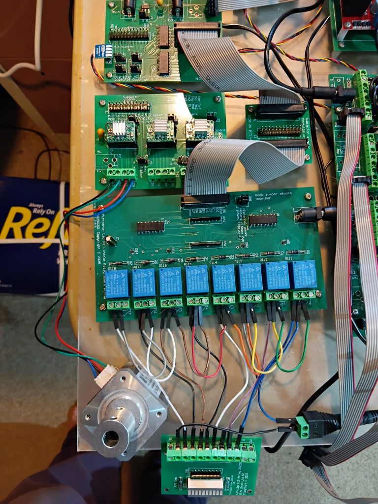
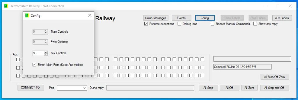
Shrinking the GUI to Aux only
One can click the Config button and adjust the number of train, pwm or auxiliary controls and also shrink the GUI window to auxiliary only.
The IOExpander board at the top of the image can drive 4 banks of eight relays, but one bank is currently shown, along with some diagnostic testing connections. Alternatively the I2C-IOExpander can drive 3 stepper motors, along with two banks of 8 relays. The stepper motors worked with old-fashioned addressable latches, but the I2C-IOExpander shown, is currently too noisy; a remedial measure is currently under development and newly designed parts are awaited for testing. There is also an older design for the I2C-IOExpander available, where there are 4 direct I2C-IOExpander connections to the relay boards. An updated relay PCB is planned, where there will be isolation slots between the relays, that would be preferable for switching mains voltages. If needed the spacing between the relays can also be increased. The digital signal on the PCB is optically isolated from the 12V supply and that is isolated by the relays from power circuitry. Not shown is the MCU that provides the I2C signal that controls the relays. The I2C connector sockets are PiicoDev, which is a commonly used socket for this purpose. 3.3V logic (RPi PIco) is currently used, but the boards are also designed for use with 5V logic, such as most Arduinos.